If you’ve ever stood next to a CNC milling machine as it carves a precise part from a solid block of aluminum or steel, you know there’s nothing quite like that mix of relief and anticipation when you pull the finished piece off the table. Every tiny step—from the moment the design file loads to the final tool withdrawal—feels high-stakes, right? As a CNC milling machine supplier, I work with shops of all sizes, from small prototype studios to large automotive manufacturers, and the question I get most often isn’t just about buying a machine. It’s how to make sure every part that comes off that machine is accurate, consistent, and ready for its job. Over the 12 years I’ve been in this business, I’ve seen too many companies waste time, money, and good parts because they skipped small, critical steps. Today, I’m breaking down the exact, practical ways to ensure your CNC-milled parts hold up to your standards—no fancy jargon, just real lessons from the floor. CNC Milling Machine
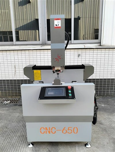
First, let’s talk about the foundation: your machine setup. Too many operators show up, load a new job, press start, and walk away, assuming the machine is calibrated. But even the best CNC milling machines drift slightly over time, especially if they’re in a busy shop running two or three shifts. Last year, I had a regular customer in the aerospace industry call me panicking because they’d run 50 small aluminum brackets that were out of spec by 0.008 millimeters—enough to get them rejected by their client. When I sent a technician out, we found their X-axis linear guide was 0.02 mm off; they hadn’t done a full machine calibration in six months. So what’s the fix here? Start with daily checks before you even load a part. Use a precision dial indicator to verify the machine’s axes are moving to the correct positions when you input a test coordinate. Most good CNC mills come with a built-in calibration tool, but don’t rely on that alone—physical checks catch the small shifts that software might miss. Also, pay attention to the environment around your machine. If your shop has windows that let in direct sun, or a ventilation fan blowing straight on the milling table, temperature changes can warp both the machine and the part as you cut. I always tell customers to keep their machine area within a consistent 68 to 72 degrees Fahrenheit; even a 10-degree shift can throw off tight tolerance parts.
Next, the tooling you use isn’t a “one size fits all” purchase, and cutting corners here is a quick path to bad parts. I once worked with a job shop owner who swore by cheap, generic end mills because they were $20 cheaper each than the branded ones we supply. He brought me parts that had inconsistent surface finishes, with small burrs along the edges, and parts that were under-sized in key locations. When we swapped to the right tool for the job—specifically, a solid carbide end mill with a polished flute and a corner radius for contour cuts—his scrap rate dropped by 18% in a month. Here’s why that matters: tool geometry, coating, and sharpness directly impact how material is removed. For soft materials like aluminum, you want end mills with more flutes to get a smoother finish, but for hard steel, fewer flutes (usually 2 or 3) let the tool clear chips without overheating. Coating also makes a huge difference: TiN (titanium nitride) works for general cutting, but TiCN (titanium carbon nitride) is better for high-speed steel, and diamond coatings are a must for machining composite materials. And don’t wait until a tool is visibly dull to replace it. A dull tool doesn’t just make a rough cut—it can pull at the workpiece, causing it to shift slightly mid-cut, leading to dimensional errors. I recommend setting a tool change schedule based on material: for aluminum, change end mills after 10 to 15 parts, and for hard steel, after 5 to 7 parts. Even if they look sharp, consistent tool changes prevent that gradual drift.
Then there’s the workpiece fixturing—how you hold the part to the milling table is just as important as the machine or the tool. I’ve seen operators use a single C-clamp to hold a small brass block, and by the time the mill finished a contour cut, the block had moved a full 0.5 mm because the clamping force wasn’t even. That’s not the machine’s fault; that’s fixturing 101. The key here is consistent, uniform clamping that distributes pressure across the entire part, not just one spot. For small parts, use a vise with soft jaws that are machined to match the part’s shape—this creates a tight, even hold without scratching the material. For larger or irregularly shaped parts, modular fixturing systems (like the ones we design for our milling machines) use grid plates and clamps that can be positioned quickly, and they eliminate the need to re-clamp parts multiple times, which reduces the chance of human error. Also, always machine a reference face first. If your part has a flat spot to clamp against, that face needs to be perfectly square and parallel to the machine’s axes. A lot of operators skip this step, especially on prototype parts, and that leads to parts that are angled or out of alignment. Before you start the main cuts, mill a small reference face using a light pass—this gives you a consistent surface to clamp against, so every subsequent cut is accurate.
Now, the part of the process that’s easy to overlook but makes all the difference: tool path and programming. I’m not a CNC programmer, but I’ve seen the mistakes that even experienced programmers make, and they turn good machines into bad part makers. Last quarter, a customer with a new 5-axis milling machine was running a complex turbine blade, and every blade had a slight notch in the leading edge. When we looked at the G-code, the programmer had set the feed rate too high for the tool’s stepover, so the tool was rubbing against the material instead of cutting it. The fix was simple: adjust the feed rate and stepover to match the tool’s capabilities. For milling, the general rule is that stepover (the distance the tool moves sideways between passes) should be 50-75% of the tool’s diameter for rough cuts, and 10-25% for finish cuts. Feed rate should be matched to the material: for aluminum, you can run a higher feed (around 200-300 inches per minute) but for stainless steel, you’ll need half that to avoid tool overheating. Also, never trust the default tool paths in your CAM software. A lot of programmers use the auto-generated paths, which might work for simple shapes but can cause vibration in complex cuts. Adding a small lead-in and lead-out to the tool path—where the tool approaches the part at an angle, instead of straight down—prevents the tool from plunging too hard, which causes chipped edges. For deep pockets, use a helical ramping tool path instead of linear plunging; that reduces stress on both the tool and the workpiece, so you get a cleaner, more accurate cut.
Once you’ve run the parts, the inspection step isn’t just checking a single part at the end—it’s a process every step of the way. I can’t tell you how many times a customer has run a whole batch of 100 parts, only to find the first 20 are correct and the last 80 are off, because the tool started to wear halfway through the run. To catch that, you need to check parts at multiple intervals, not just the end. For high-tolerance parts, I recommend checking the first part right after setup, then every 10 to 15 parts, and the last part before you unload the machine. Use the right inspection tools too: a digital caliper works for rough dimensions, but for tolerances tighter than 0.01 mm, you need a coordinate measuring machine (CMM) or a micrometer, and a surface roughness tester to make sure the finish meets specifications. A lot of shops skip surface roughness checks, but a part that looks “good” to the eye might have micro-roughness that causes it to fail in its application—like a hydraulic seal that leaks because the surface isn’t smooth enough. Also, keep a log of every part you run: record the tool number, feed rate, spindle speed, temperature, and inspection results. This log is gold if you ever have a problem; you can go back and see if the issue was tool wear, temperature, or a programming mistake. I had a customer in medical devices use a log like this to track a problem with titanium parts; they found that every time the shop ran a full batch, the spindle temperature rose by 5 degrees, which caused the part to expand and shift. They adjusted the spindle to warm up for 10 minutes before starting the run, and the problem was solved.
Now, I want to be honest with you—even when you do all these steps, you’re going to have some scrap parts. That’s not a failure; it’s part of working with CNC milling. The difference between a shop that succeeds and one that struggles is how they handle the small details I’ve talked about. As a CNC milling machine supplier, my job isn’t just to sell you a machine—it’s to make sure it works for you. We don’t just deliver the machine and walk away; we provide on-site training for operators, regular calibration checks, and help picking the right tooling for your specific parts. Whether you’re making small prototypes or large production runs, the right machine paired with these practices will keep your parts consistent and high-quality.
If you’re tired of dealing with scrap parts, inconsistent cuts, and expensive downtime, let’s connect. We can talk about your specific needs, walk through the steps that will work for your shop, and make sure your CNC milling process is as efficient and reliable as it should be. Whether you’re upgrading your current machine or investing in a new system, we’re here to help every step of the way.
Cutting Machine References:
- Smith, J. (2021). CNC Milling: Principles, Setup, and Quality Control. Industrial Press
- Brown, A. (2022). Tooling and Fixturing for High-Precision Machining. Manufacturing Engineering Magazine
- Davis, R. (2020). Temperature Control in CNC Machining: Impact on Part Accuracy. Journal of Machining Science and Technology
Kanghong Building Materials Technology Sdn. Bhd.
As one of the most professional CNC milling machine manufacturers and suppliers in China, we have world-leading production equipment and strong manufacturing capabilities. Please feel free to wholesale advanced CNC milling machine for sale here from our factory. Customized orders are welcome.
Address: No.601, Block 2, Xinlianchang Industrial Park, No.2 Taixing Second Road, Taiping South Industrial Zone, Dali Town, Nanhai District, Foshan City
E-mail: 631871392@qq.com
WebSite: https://www.kanghong-building.com/
